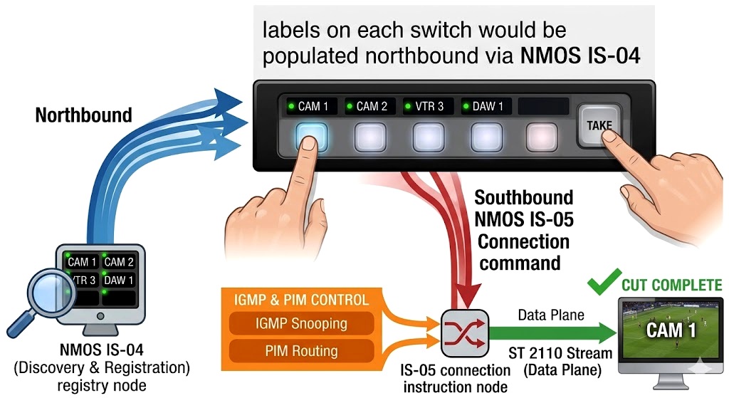
This graphic visualizes how a simple physical action—pressing a button on a router panel—ripples through the entire OSI stack.
Here is the breakdown of what that specific graphic is showing:
The Human Intent (The "Button Push")
At the top of the graphic, you see a traditional, hardware-based XY Router Control Panel (like a Riedel, Ross, or GV panel). This is the bridge between the physical world and the Application Layer (Layer 7). The operator presses a button labeled "CAM 1" to "MON 1."
The Labeling
The graphic shows a data flow where the panel gets its names.
The Logic: The panel doesn't "know" what is plugged into Port 1.
It asks the NMOS Registry: "What is at this IP address?"
The Result: The Registry responds, "That's Camera 1," and the small LCD screen on the button updates.
This is the "Discovery" phase.
The Execution
When the "Take" button is pressed, the graphic shows a command arrow moving from the Control Panel to the "Orchestrator" (The Brain).
The Command: The Orchestrator sends an IS-05 Connection Management command to the destination device (the Monitor).
The Message: "Drop your current stream and Join Multicast Group 239.1.1.1."
The Network Handshake (IGMP & PIM)
The graphic then moves down into the Network Fabric (the Cisco/Arista switches).
IGMP Join: The Monitor sends an **IGMP** request to the switch port.
PIM & Snooping: The switch "snoops" this request and uses PIM (Protocol Independent Multicast) to find the source of Camera 1.
The Result: The switch opens the "gate," and the packets begin to flow to the monitor.
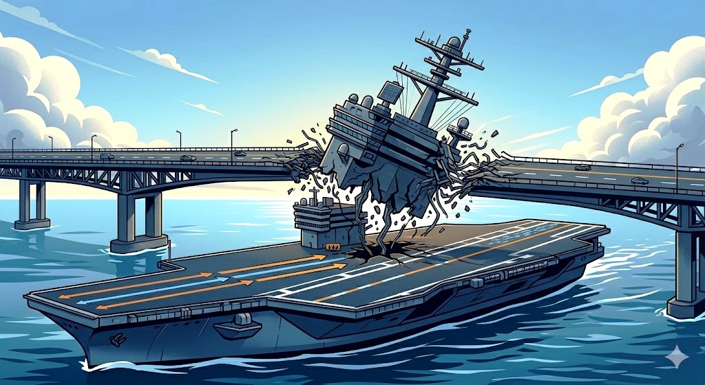
Using this graphic as a metaphor
In the Button Push graphic, the Control Panel and Orchestrator are the "Island" of the ship. They handle the naming and the ordering.
The IGMP/PIM and the Switch Fabric are the "Hull." They don't care about the names "CAM 1" or "MON 1. They only care about the IP addresses and the bandwidth.